Many HIL test systems require a hardware fault injection to simulate faults between the DUT and the rest of the system. The Routing and Faulting Custom Device injects faults by using switching and fault insertion modules. The SLSC Switch Custom Device provides hardware support for SLSC Switch routing modules.
The routing module acts as a gatekeeper between the DUT and the I/O. A common configuration in a fault injection application is a "fault bus topology." In this topology, endpoints are shorted to one or more buses.
The following table displays common topology states.
| States | Description | Diagram |
|---|---|---|
| Passthrough | The DUT and the I/O are connected without fault. This is the default state. | 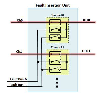 |
| Open Circuit | The DUT and the I/O are not connected, simulating an open circuit. | 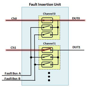 |
| Short to Ground | The DUT and the system ground are connected, simulating a short to ground. | 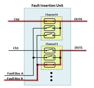 |
| Short to Power | The DUT and the system power are connected, simulating a short to power. | |
| Pin-to-Pin Short | Two or more DUT pins are connected, simulating a pin-to-pin short. | 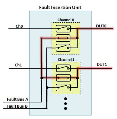 |
The SLSC Switch Custom Device is a VeriStand add-on that supports SLSC routing modules. The following modules are supported:
SLSC Switch routing modules are displayed in the VeriStand System Explorer under Targets >> Controller >> Hardware >> SLSC >> SLSC Chassis >> Modules >> Slot (n).
The following image displays this location.

The SLSC Switch Custom Device enumerates all available endpoints for a routing module. Set the configuration for each endpoint to inform the SLSC Switch driver of valid endpoints to connect to.
The following table describes the available endpoint configurations.
| Configuration | Description |
|---|---|
| Load | A load endpoint is unrestricted and can be connected to other load and source endpoints. This is the default configuration for an endpoint. |
| Source | A source endpoint is restricted and cannot be connected to another source endpoint. |
| Configuration | A configuration endpoint is reserved by the hardware for internal routing. This configuration cannot be used directly. |
NOTE: Configure the SLSC Switch Custom Device before configuring the Routing and Faulting Custom Device.
The SLSC Switch Custom Device initializes its SLSC Switch session with a custom reservation group. This initialization allows SLSC sessions with the same group to concurrently reserve the device. Avoid modifying SLSC properties used by SLSC Switch through these external sessions, as this will corrupt the switching state and establish unintended connections.
Use SLSC Switch 20.0.1 or newer to apply the reservation group. If you use SLSC Switch 19.x or 20.0.0, the custom device will silently ignore the reservation group.
By default the reservation group for the SLSC Switch Custom Device is the path to the module in the system definition file. Use the scripting API to update this value.
The NI-SWITCH Custom Device is a VeriStand add-on that supports NI-SWITCH PXI routing modules.
NI-SWITCH routing modules are displayed in the VeriStand System Explorer under Targets >> Controller >> Custom Devices.
The following image displays this location.

The NI-SWITCH custom device supports the same endpoint configuration options as the SLSC Switch custom device.
NOTE: Configure the NI-SWITCH Custom Device before configuring the Routing and Faulting Custom Device.
The Routing and Faulting Custom Device is a VeriStand add-on that configures aliases and routing channels. By default, routing channels are not added. Add routing channels for each controllable collection of connections.
Routing Channels are displayed in the VeriStand System Explorer under Targets >> Controller >> Custom Devices >> Routing and Faulting >> Routing Channels.
The following image displays this location.

Each routing channel contains one or more user-defined states. Common states for a fault injection application include Passthrough, Open Circuit, Short to Ground, Short to Power, and Pin-to-Pin Short. By default, the Open Circuit state is added. Add additional states to match the requirements of the fault injection application.
Each state contains a collection of connections. Each connection consists of a source and destination endpoint on a routing module. By default, no connections are added. Add connections to establish connections between the DUT and the I/O. A single connection cannot span multiple routing modules. Define multiple connections, one for each routing module, to connect a signal spanning multiple routing modules.
Map a ring control on a VeriStand screen to a routing channel to set the current state. Set the current state to change the active connections between the DUT and the I/O. Existing connections from the previous state are disconnected before new connections from the current state are connected. Connections that remain unchanged from the previous state to the current state are not modified.
The following image displays how to configure a ring control on the VeriStand Editor.

The Scripting API uses LabVIEW VIs to configure modules, endpoints, aliases, and routing channels in a VeriStand system definition file.
Note: The SLSC Switch Custom Device must be assigned to a slot in the SLSC Chassis Custom Device before running the example. The SLSC Chassis Custom Device is displayed in the VeriStand System Explorer under Targets >> Controller >> Hardware >> SLSC >> SLSC Chassis.
Open the scripting examples on disk from Source/Scripting Examples/Scripting Examples.lvproj. Run Configure Modules from Hardware.vi to configure one or more SLSC Switch routing modules in the system definition file.
The following image displays the Configure Modules from Hardware.vi.

Run Configure Routing and Faulting Custom Device.vi to add routing channels, states, and connections. The example adds two routing channels named Window Up and Window Down. Both routing channels have possible states of No Connections, Passthrough, Short to Ground, Short to Power, and Open Circuit. The Window Up routing channel connects the DUT_Ch0 endpoint to the fault buses. The Window Down routing channel connects the DUT_Ch1 endpoint to the fault buses.
The following image displays the Configure Routing and Faulting Custom Device.vi.

Open the scripted system definition file in VeriStand to review the configuration or deploy the project.
alias An alias is an alternate name for an endpoint for improved readability. Alias endpoints to match application DUT pins or I/O.
connection A connection consists of a source and destination endpoint on a routing module. The routing module closes one or more switches to establish a connection. The routing module opens one or more switches to break a connection.
DUT The device under test (DUT) is the hardware being tested for faults. The DUT may be an electronic control unit (ECU) or a line-replaceable unit (LRU).
endpoint An endpoint is a source or destination pin on a routing module. A typical application connects the DUT pins or I/O to endpoints. In NI Switch or NI SLSC Switch this is also known as a channel.
HIL Hardware in the loop.
I/O Input/output.
routing channel A VeriStand routing channel consists of one or more potential states and a current state. The current state determines which connections are active.
state Each state consists of zero or more connections. The Scripting API creates a single state with no connections for the initial state by default.
Using Fault Insertion Units (FIUs) for Electronic Testing
Save Time and Maximize Reuse in HIL Testing with the SLSC Extension for PXI and CompactRIO
Using the SLSC-12251/2 Fault Insertion and Current Sensing Unit